|
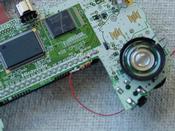
The resistor - note that the leads are trimmed down alot and bent to
hit pin S2 exactly as well as avoid the flange sticking down from the GBA
mainboard.
|

|
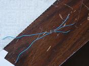
The dimmer chip with wires on all pins except 5 and 6, which go to the
Afterburner light itself.
|

|
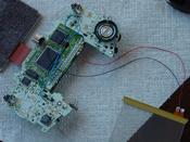
Note the dimmer chip "glued" to the mainboard via liquid electrical tape
in a spot where none of the pins would touch any stray mainboard contacts.
I applied the liquid electrical tape to the bottom of the dimmer chip
using a cut-off Q-tip (no fuzzies) and then taped it down with electrical
tape until the liquid electrical tape dried enough to hold the chip.
|

|
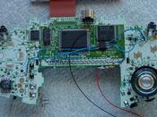
Closeup of the wiring additions to the mainboard. The black wire is simply
stripped of insulation far enough to fold over both pins 5 and 6, where it's
soldered to each pin.
|


